What makes the boundary relevant?
Heated water needs somewhere to displace its added volume. A verified one-way arrangement can isolate the heater from an upstream volume. Amtrol MC10007 (opens source in a new tab) identifies backflow preventers, check valves and pressure-reducing arrangements in that context. Device function and placement matter more than whether the house is described as city-fed or well-fed.
A regulator may include model-specific bypass behavior, and another check device may still block an upstream path. The PRV guide explains why seeing a bell-shaped body does not establish a complete boundary. Keep an uncertain function or path unknown until the model or installation drawing is verified.
An open path to a well tank is a conditional observation
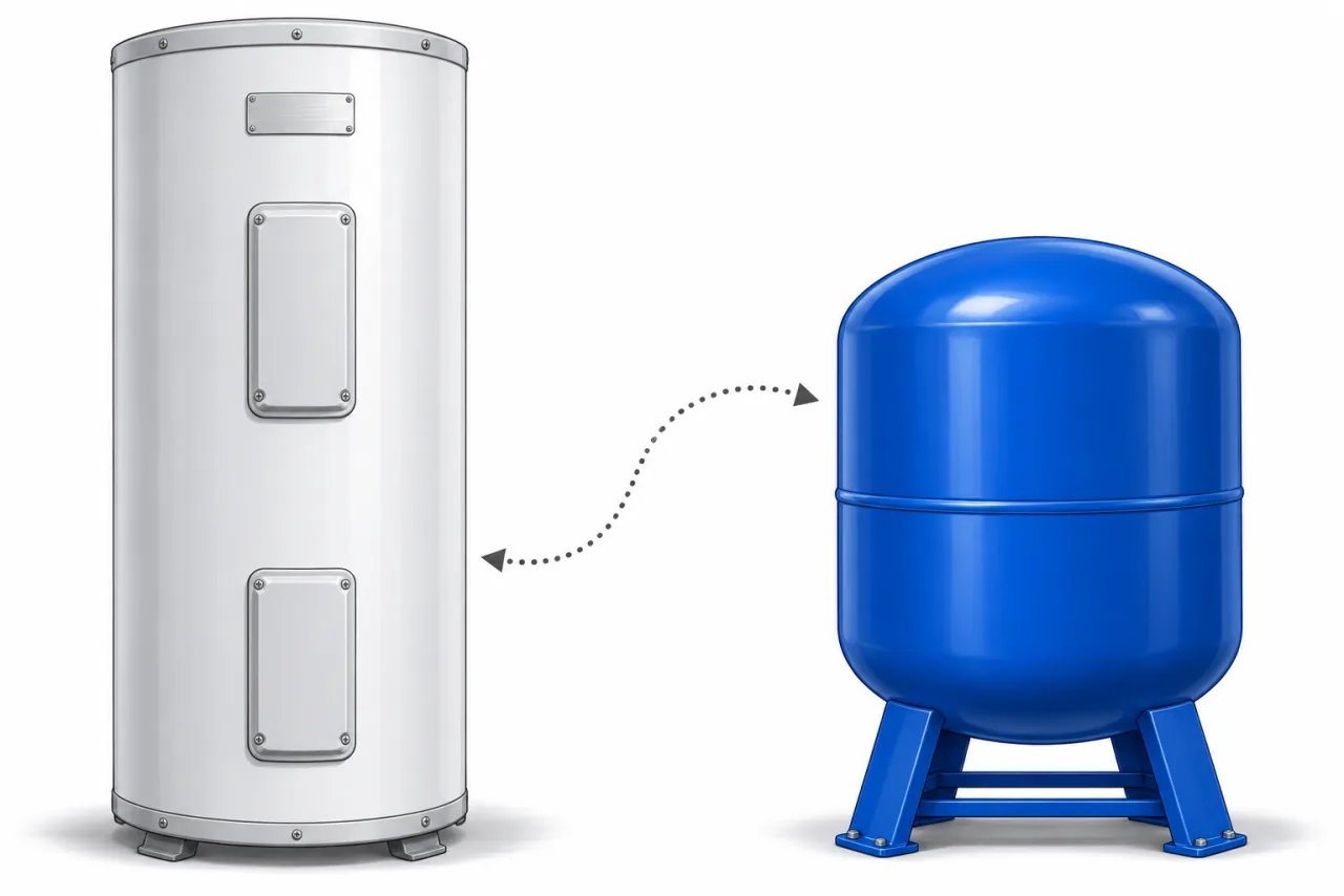
If a verified pipe path communicates with a functioning well pressure tank, that tank may offer expansion acceptance. This is a physical-path inference, not a blanket exemption from expansion control. Its available acceptance, operating pressures, any downstream checks and the applicable product and local requirements still need review. The form therefore records communication; it does not answer “no separate tank required.”
Compare three situations
| Recorded arrangement | What the record supports | Still unresolved |
|---|---|---|
| Well tank communicates with heater, no intervening one-way boundary verified | A potential displacement path exists. | Available acceptance and installation requirements. |
| Check device between well tank and heater | The heater can occupy an isolated sub-circuit. | Required expansion control for that actual circuit. |
| New meter or treatment device, function not verified | The prior drawing may no longer describe the system. | Device model, flow path and any bypass. |
Make a record an installer can use
- Name the source
Record the municipal or well supply and any pressure-tank model already documented.
- Name the evidence
Use an existing drawing, model manual or installer statement. A guess based on appearance should remain unknown.
- Keep the path together
List where the heater branch and any regulator, check or treatment assembly sit relative to one another. Do not dismantle a device to complete this form.
- Ask the specific question
Does expanded water have a verified return path, and is the available acceptance adequate under the applicable design conditions?
The Amtrol placement FAQ (opens source in a new tab) gives a product-specific principle: place its thermal expansion tank on the heater side of a backflow/check valve, at the cold inlet. It does not certify a particular well pressure tank as a substitute. If the boundary is confirmed isolated, continue to the manufacturer method comparison rather than choosing a familiar vessel size.
Sources and limits
Reviewed 2026-11-15. The linked method and your model manual take precedence over an explanatory example.
- Amtrol MC10007 · sizing and placement (opens source in a new tab)
03/19. Pages 2–3: 40°F-base factors, DPF, pre-charge example and placement. Manufacturer-specific guidance; local and model requirements still apply.
- Amtrol · plumbing and hot-water support (opens source in a new tab)
Live FAQ. Pre-charge matching, cold-inlet location and supported orientation. Use the installation manual for the actual model.
- Watts LFRC105 · bypass and high pressure (opens source in a new tab)
IS-LFRC105 1633 (2016). Page 1: this regulator’s bypass behavior and possible high-pressure causes. Not a rule for every PRV.