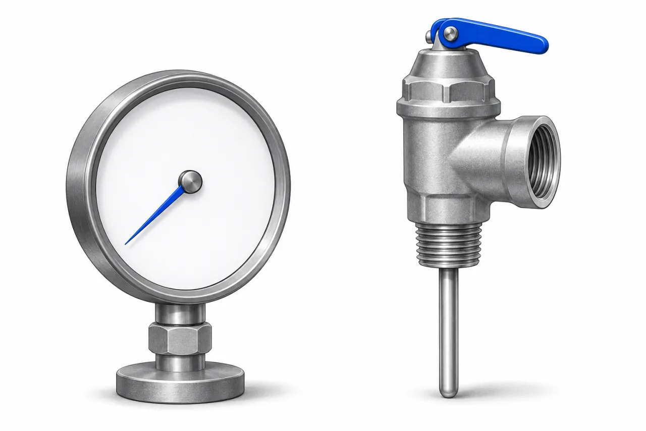
Three different pressure fields
Illustrative values, not measurements of a home.
- Static supply
- The recorded baseline at the stated location and condition.
- Design ceiling
- A design condition taken from the applicable method or installer.
- Relief rating
- The safety valve’s rating; not a routine operating target.
Keep four kinds of pressure separate
| Value | Record alongside it | Avoid this substitution |
|---|---|---|
| Static pressure | No-flow condition, location, date and source of reading. | A flowing value or an unexplained retained peak. |
| Retained peak | Observation window, instrument and whether heating occurred. | A diagnosis of why the peak occurred. |
| Design ceiling | Applicable method or installer reference. | The stamped relief-valve rating. |
| Relief rating | Actual valve and heater/component ratings. | A routine operating target. |
What a bypass example can actually establish
The Watts LFRC105 instructions (opens source in a new tab) describe that regulator’s built-in bypass and state a downstream limit relative to supply pressure of 10 psi. The same instructions warn that the bypass cannot prevent relief opening for sufficiently high supply conditions. This is not a universal crack-pressure formula, and it does not justify claiming a generic peak of “street pressure plus 1 psi.”
For an illustrative 115 psig supply, even the supply value itself is above an 80 psig design goal. A return path that depends on rising above that supply cannot be assumed to hold the downstream circuit below the lower goal. That comparison explains the limitation without predicting a particular peak or declaring what happens on every cycle. Other check/backflow devices and the actual regulator model must also be considered.
High pressure does not identify a failed part
The LFRC105 troubleshooting section lists thermal expansion, pressure creep and material on a valve seat as possible causes of high downstream no-flow pressure. Those are manufacturer troubleshooting possibilities, not a ranking or diagnosis for an unknown installation. A high reading alone cannot establish whether a regulator needs replacement, whether an expansion tank failed or which repair is appropriate.
Why our arithmetic stops outside its scope
The Watts ETP tool · source record describes a typical static-pressure/code context and its own pre-charge and final-pressure limits. This site does not convert that tool note into a universal nationwide rule for every product. Our worksheet accepts static records only from 20 to 80 psig, withholds higher records and asks for applicable manufacturer or professional review. An excluded value must not be adjusted in the equipment just to obtain a result.
A source-linked pressure record
Record the source or street reading separately from the downstream reading, identify the regulator model, and retain the timing and type of each reading. List any meter, treatment or check devices already documented. Then ask which design limit and expansion method applies to that actual circuit. If discharge accompanies the concern, use the observation guide to keep safety and diagnosis separate.
Sources and limits
Reviewed 2026-11-15. The linked method and your model manual take precedence over an explanatory example.
- Watts LFRC105 · bypass and high pressure (opens source in a new tab)
IS-LFRC105 1633 (2016). Page 1: this regulator’s bypass behavior and possible high-pressure causes. Not a rule for every PRV.
- Watts · potable expansion sizing conditions · source record
Live tool instructions. Distinct initial/final pressure and temperature conditions. Its 85%-of-relief ceiling and 90°F starting-water note must not be silently mixed with another method.
- A.O. Smith · relief-valve Bulletin 52 (opens source in a new tab)
Bulletin 52; publication date not stated. Temperature/pressure relief roles and rating limits. An observation form cannot establish a specific fault.